TMO Layout & Specifications
A review of the current TMO beamline can be found here: The time-resolved atomic, molecular and optical science instrument at the Linac Coherent Light Source
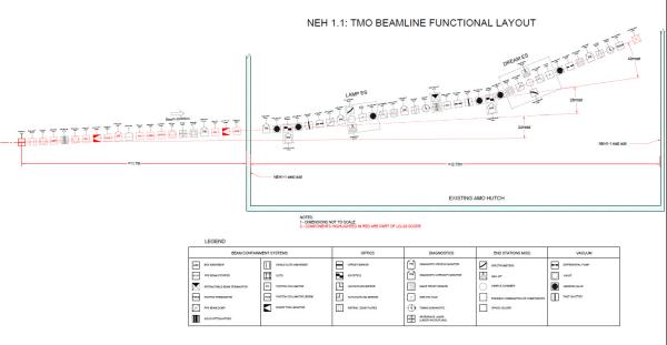
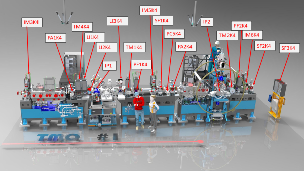
The time-resolved atomic, molecular and optical science (TMO) instrument at the Linac Coherent Light Source has multiple instruments to enable a wide-range of gas phase experiments. Some beamline components and diagnostics will be placed in the front end enclosure (FEE) as shown in the functional layout below. This hutch features two interaction points IP1 and IP2, where experimental end stations can be installed. IP1 can offer several end station configurations, as detailed below. IP2 is more specializied for the reaction microscope end station called DREAM.
NEH 1.1 Functional Layout
EndStations
A first KB mirror pair focuses the beam to the first interaction point of the TMO hutch. TMO has several modular endstations which can be installed in IP1. A second pair of KB optics demagnifies the IP1 focal spot to sub-micron size. IP2 features a fixed endstation, the DREAM endstation.
MBES:
The TMO magnetic bottle electron spectrometer (MBES) features a 2.1 m flight tube and an electrostatic lens to retard high-energy photo-electrons, for improved kinetic energy resolution. At the interaction point, an inhomogenous field is created by a permanent magnet. A flat copper plate is attached to the nose cone, which enables the application of a uniform electric field across the interaction region by applying a voltage to the magnet. The flight tube creates a uniform solenoid field to direct electrons to the MCP detector. This detector is coupled to a dual anode which allows for some radial-discrimination of the measured spectrum.
Refs:
Kurtis Borne, Jordan T. O’Neal, Jun Wang, Erik Isele, Razib Obaid, Nora Berrah, Xinxin Cheng, Philip H. Bucksbaum, Justin James, Andrei Kamalov , Kirk A. Larsen , Xiang Li, Ming-Fu Lin, Yusong Liu, Agostino Marinelli, Adam M. Summers, Emily Thierstein, Thomas J. A. Wolf, Daniel Rolles, Peter Walter, James P. Cryan, Taran Driver (2024) Rev. Sci. Instrum. 95, 125110
MBES Spectrometer Properties
Spectrometer Type | Electron Time of Flight (2.1 m flight tube) |
|---|---|
Detector Properties | 40 mm MCP coupled to dual anode readout |
Energy Resolutuion | DE/E < 5% |
Retardation up to 200 V | |
Sample Delivery | Heated Gas Needle or |
In-Vacuum Oven | |
Additional considerations | Ion extraction optics for coincident ion ToF capability currently under development |
MRCO:
This endstation features an angle-resolving array of up to 20 electron time-of-flight spectrometers, which allow a wide and adjustable energy acceptance window. By interleaving detector retardations, MRCO enables simultaneous angle-resolved spectroscopy of electrons with disparate energies.
Refs:
Walter, P., et al. J. Synchrotron Rad. (2021). 28, 1364-1376
MRCO Spectrometer Properties
Spectrometer Type | Electron Time-of Flight |
|---|---|
16 eToFs in an angular array about the plane perpendicular to the x-ray propagation direction | |
4 eToFs at the magic angle (54.7 deg) in the forward direction | |
Detector Properties | 12 mm diameter, funnel-type MCPs |
Spectrometer Resolution | DE/E < 1% |
Angular acceptance 1.5o-3.0o | |
Retardation up to 2000 V | |
Sample Delivery | Heated gas needle |
cVMI:
The coaxial VMI (cVMI) endstation provides an electron VMI spectrometer where the ionizing laser source propagates along the symmetry axis of the spectrometer. This device provides a unique two-dimensional projection of the three-dimensional electron momentum distribution. The charged particles are detected by an 80 mm microchannel plate coupled to a fast phosphor screen imaged by a fast CCD camera. In addition to the VMI spectrometer, this endstation offers a skimmed molecular beam source.
Refs:
Li, S., Champenois, E. G., Coffee, R., Guo, Z., Hegazy, K., Kamalov, A., Natan, A., O'Neal, J., Osipov, T., Owens, M., Ray, D., Rich, D., Walter, P., Marinelli, A. & Cryan, J. P. (2018). AIP Adv. 8, 115308.
cVMI Spectrometer Properties
Spectrometer Type | Velocity Map Imaging spectrometer |
|---|---|
Detector Properties | 80 mm diameter MCP coupled to fast phosphor screen. Imaged by low frame rate (120 Hz) camera |
Spectrometer Resolution | DE/E~10%, ~500 eV maximum electron energy for full collection |
Sample Delivery | Skimmed molecular beam source with single skimmer stage. |
oriented vertically | |
Additional Consideration | Can be used as an x-ray pulse diagnostic |
dVMI:
This is a double-sided velocity map imaging spectrometer. We can detect ions and/or electrons allowing for simultaneous measurements of all charged particles generated by photoionization of a single atom/molecule. The spectrometer features a long and short arm. Charged particles in the long arm are detected with a MCP coupled to a quad-anode detector, whereas particles in the short arm are detected with a MCP coupled to a fast phosphor screen imaged by a fast CCD camera. This spectrometer is designed to mount in the multi-purpose LAMP chamber. LAMP features a doubly skimmed molecular beam source.
Refs:
Osipov, T., Bostedt, C., Castagna, J. C., Ferguson, K. R., Bucher, M., Montero, S. C., Swiggers, M. L., Obaid, R., Rolles, D., Rudenko, A., Bozek, J. D. & Berrah, N. (2018). Rev. Sci. Instrum. 89, 035112.
dual VMI Spectrometer Properties
Spectrometer Type | Velocity Map Imaging (coincident electron/ion detection) |
Detector Properties | Electron side (short arm) 120 mm diameter MCP coupled to fast phosphor screen. Imaged by low frame rate (120 Hz) camera |
Ion side (long arm) 80 mm diameter MCP coupled to quad-anode | |
Spectrometer Resolution | Electron side (short arm): DE/E~10%, 400 eV max electron energy for full collection |
Ion side (long arm): 50 eV max ion kinetic energy for full collection | |
Sample Delivery | Skimmed Molecular beam, dual skimmer |
Mounted in horiziontal orientation |
kToF:
TMO has a Kaesdorf ETF11B electron time-of-flight spectrometer which can be attached to either the LAMP or cVMI chambers.
Refs: ETF11
KToF Spectrometer Properties
Spectrometer Type | Electron Time-of-Flight Spectrometer |
Detector Properties | MCP coupled to conical anode |
Spectrometer Resolution | DE/E ~ 1% |
45o Collection Angle | |
400 V retardation lens |
DREAM:
The Dynamic REAction Microscope (DREAM) endstation is a cold target recoil ion momentum spectroscopy (COLTRIMS) type spectrometer, which can detect both electrons and ions coincidently. The standard detectors for DREAM are two 120 mm state-of-the-art Hexanode delay-line detectors.
Refs:
Walter, P., Holmes, M., Obaid, R., Amores, L., Cheng, X., Cryan, J. P., Glownia, J. M., Li, X., Lin, M.-F., Ng, M.-L., Robinson, J., Shivaram, N., Yin, J., Fritz, D., James, J., Castagna, J. C., Osipov, T. (2022) Appl. Sci. 12, 10534.
DREAM Spectrometer Properties
Spectrometer Type | Reaction Microscope type coincident electron/ion spectrometer |
Flat-field charged particle extraction | |
Detector Properties | 120 mm diameter MCP coupled to hex-anode readout for both ion and electron sides |
Sample Delivery | Skimmed molecular beam source |
4 skimmer stages | |
mounted vertically |
X-ray Imagers (IM#)
We have several x-ray imagers to measure the beam size and position along the TMO beamline. Each imager features a power meter to measure the beam transmission downstream of every mirror system.
References:
Heimann, P. A., Fritz, D., Krzywinski, J., Moeller, S., Nordlund, D., Reid, A., Stefan, P., Walter, P. & Welch, J. (2019b). Proc. SPIE, 11038, 40-43.
Laser In-Coupling (LI1 and LI2)
The TMO hutch has two standard options for in-coupling an external laser pulse. The upstream in-coupling mirror (LI1), features an off-axis mirror which produces a crossing angle of <0.5 deg between the laser pulse and the x-ray propagation. This in-coupling mirror is intended for use with short wavelength (< 800 nm) pulses. Additionally a downstream in-coupling mirror (LI2) features a mirror with a hole to provide co-propagating laser/x-ray pulses. LI2 is intended for long wavelength (>800 nm) laser pulses.
Laser Out-coupling (LI3)
The external laser pulse is out-coupled by an additional mirror (LI3) downstream of the interaction point. This device features diagnostics to facilitate the spatial and temporal alignment of the external laser pulse.
Arrival Time Monitor (ATM1/2)
After each interaction point we have a device to measure the relative arrival time between the external laser pulse and the x-ray pulse.
References:
Stefan Droste, Sioan Zohar, Lingjia Shen, Vaughn E. White, Elizabeth Diaz-Jacobo, Ryan N. Coffee, Alexander H. Reid, Franz Tavella, Michael P. Minitti, Joshua J. Turner, Joseph S. Robinson, Alan R. Fry, and Giacomo Coslovich (2020) Opt. Express 28, 23545-23553
Wavefront Sensors (PF1/2)
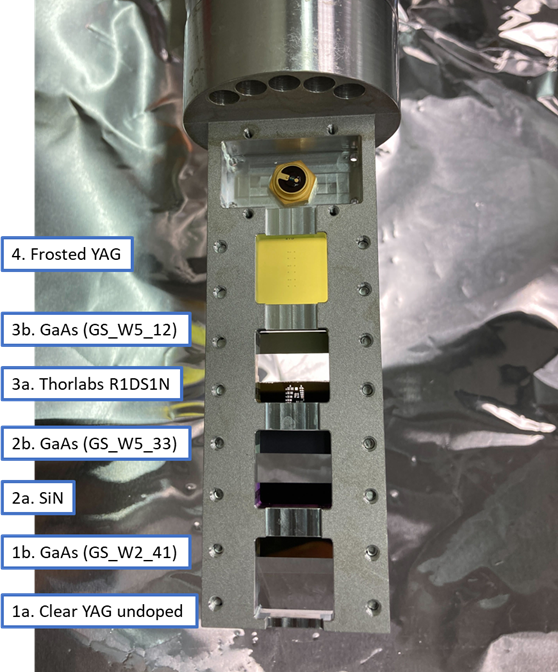
Each interaction point in the TMO hutch is equipped with a wavefront sensor (WFS) to diagnose the focus properties. The sensors make use of the fractional Talbot effect to measure the wavefront. The WFS can be operated in both an averaging mode accepting nearly the total energy available from the FEL, but also in a single-shot mode at reduced (<10 Hz) repetition rate.
References:
Liu, Y., Seaberg, M., Feng, Y., Li, K., Ding, Y., Marcus, G., Fritz, D., Shi, X., Grizolli, W., Assoufid, L., Walter, P. & Sakdinawat, A. (2020). J. Synchrotron Rad. 27, 254-261.
Photon Spectrometer (SP1)
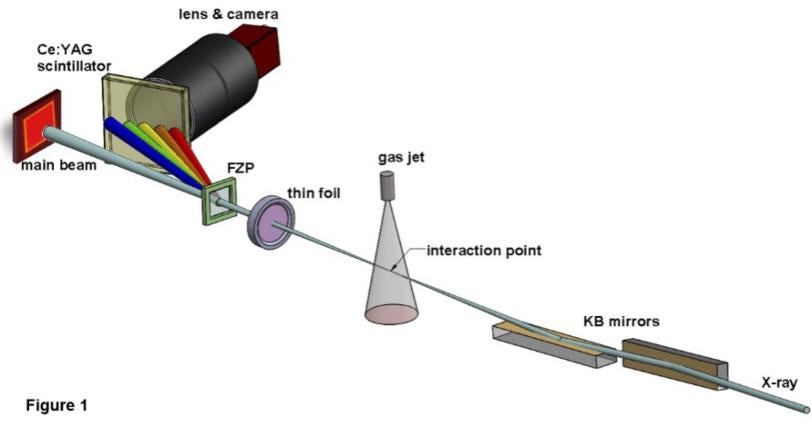
Downstream of the first interaction the TMO hutch has a single-shot spectral diagnostic. This device is based on an off-axis Fresnel zone plate, which disperses and focuses the beam to measure the spectral profile. This compact photon spectrometer has a designed resolving power of ~1000 which we have demonstrated at the oxygen K-edge. The resolution is sufficient to resolve the SASE sub-structure as shown in the figure. The single-shot spectrum is recorded to the data set along with other detectors.
References:
Larsen, K.A., Borne, K., Obaid, R., Kamalov, A., Liu, Y., Cheng, X., James, J., Driver, T., Li, K., Liu, Y., Sakdinawat, A., David, C., Wolf, T.J.A., Cryan, J.P., Walter, P., and Lin, M.F. (2023) Optics Express 31, 35822-35834
X-Optics
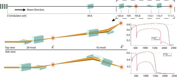
The primary X-ray focusing optics in TMO are pairs of Kirkpatrick-Baez mirrors. Each mirror pair has two reflection zones, one B4C coated and one bare Si, to facilitate a maximum transmission over the energy range covered by TMO. The incident angles with respect to the mirror surface are 14 mrad and 21 mrad for the first and second pair of KB mirrors, respectively. These incident angles allow for an X-ray energy range of 250–2200 eV in the first interaction point (IP1) and an energy range of 250–1400 eV for the second interaction point (IP2). The first pair of mirrors are bendable in a plane-elliptical geometry which enables the foci to be varied along the beamline, and the focus dimension can change from below 1 µm to about 200 µm FWHM. Beyond translating the focus, the first pair can be used to compensate for the aberration of the second pair of mirrors which are not bendable. The average focal length of the KB mirror pairs are 2 m and 0.6 m, respectively.
Refs:
Seaberg, M., Lee, L., Morton, D., Cheng, X., Cryan, J., Curiel, G. I., Dix, B., Fox, K., Hardin, C., Li, K., Li, X., Lin, M.-F., Liu, Y., Montagne, T., Obaid, R., Sakdinawat, A., Whitney, R., Wolf, T., Zhang, L., Fritz, D., Walter, P., Cocco, D. & Ng, M. L. (2022). Synchrotron Radiat. News.
Spec | Value | Unit |
|---|---|---|
X-ray incidence angle | 14 | mrad |
Shape | Elliptical (multiple polished sections) | - |
Length | 600 (550) | mm |
Coating stripe width | ≥ 10 | mm |
Coating Material | B4C and Bare Silicon |
|
Number of stripes | ≥ 4 | - |
Total mirror width | ≥ 65 | mm |
Mirror gap | ≤ 80 | mm |
Focal spot size (min) | < 1 | μm |
Focal spot size (max) | 100 | μm |
Spec | Value | Unit |
|---|---|---|
X-ray incidence angle | 21 | mrad |
Shape | Elliptical | - |
Length | 360 (340) | mm |
Coating stripe widths | ≥ 7 | mm |
Coating Material | B4C and Bare Silicon |
|
Number of stripes | ≥ 2 | - |
Total mirror width | ≥ 30 | mm |
Mirror gap | 20 | mm |
Focal spot size (min) | 0.3 | μm |
Focal spot size (max) | 20 | μm |
Beamline Devices
Beamline Specifications
Parameter | Value |
|---|---|
Undulator Source | SXU |
Photon Energy Range | 250-2000 eV |
Focused Beam Diameter (FWHM) | < 1.5 μm (IP1) & < 300 nm (IP2) |
X-ray Bandwidth | 3 × 10⁻³ 1 × 10⁻⁴ (seeded) |
Beamline Transmission | ~ 80% (IP1) & ~ 60% (IP2) |
Repetition Rate | up to 929 kHz |
X-ray Power Limit | 200 W |
Optical Laser | 200 nm to 17 μm with varying power, repetition rate, and pulse duration |
Primary X-ray Techniques |
|
TMO Contacts
James Cryan
TMO Instrument Lead
(650) 926-3290
jcryan@slac.stanford.edu
Jeff Aldrich
Area Manager
jaldrich@slac.stanford.edu
Thomas Wolf
Lead Scientist
(650) 926-2533
thomas.wolf@slac.stanford.edu
Taran Driver
Staff Scientist
tdd14@slac.stanford.edu
Ming-Fu Lin
Staff Scientist
(650) 926-2586
mfucb@slac.stanford.edu
Ruaridh Forbes
Laser Scientist
ruforbes@slac.stanford.edu
Mike Glownia
Laser Scientist
jglownia@slac.stanford.edu
Xiang Li
Associate Scientist
xiangli@slac.stanford.edu
Razib Obaid
Associate Scientist
robaid@slac.stanford.edu
Mat Britton
Associate Laser Scientist
matb@slac.stanford.edu
Justin James
Staff Engineer
(650) 926-3842
jhjames@slac.stanford.edu

