XCS Components
A comprehensive overview of the XCS instrument is published in
Journal of Synchrotron Radiation, 22, (2015).
The XCS instrument is a dedicated LCLS instrument for the use of Coherent X-ray Scattering techniques in general and X-ray photon Correlation Spectroscopy in particular. It can operate in the hard X-ray range (5.5-25 keV) on any of the harmonics of LCLS.
Monochromaticity

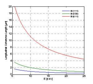
The XCS instrument operates mainly in monochromatic beam but it can also operate in pink beam if scientifically required. By default the XCS instrument will be providing Si(111) monochromaticity.
| Longitudinal Coherence Length [μm] | ||||
|---|---|---|---|---|
| Crystal | Δλ/λ | 8 keV | 16 keV | 25 keV |
| Si(111) | 1.36 x 10⁻⁴ | 1.14 | 0.56 | 0.36 |
Focusing
The beam can be focused by inserting Beryllium compound refractive lenses in the beam path. The focal length can be adjusted for a given X-ray energy by selecting an appropriate number of individual lenses (up to 10) and stacking them. One can switch from one stack to another (up to three) remotely. Such a unit is located 3.3 meters upstream from the sample. Each unit has the capability to be translated longitudinally ±0.3 m. This allow some tunability in the beam size at the sample when not working at the focus.
Diffractometer

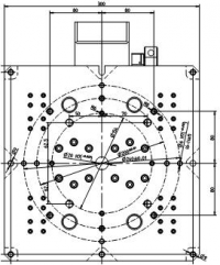
The XCS instrument is providing a horizontal scattering 4-circle Huber diffractometer. It has a local 2θ detector arm to easy crystal alignments. It can be removed from the beam path for accommodating large sample environment that are not compatible with the diffractometer. The top surface of the diffractometer is 300 x 300 mm2. The distance between the top surface of the diffractometer and its center or rotation is 270 mm.
Sample Environments
The XCS instrument will try to provide a complete suite of sample of environments to the user community. This will however happen along the operation of XCS. At the beginning of the operation of XCS, no sample environment may be provided and the users are expected to provide their own favorite sample environment. Any integration issue should be discussed with the XCS instrument team.
Large Angle Detector Mover

The XCS instrument has a Large Angle Detector Mover as a long sample-detector 2θ arm. It was build by FMB/OXFORD. The LADM provides two sample detector distances : 4 and 8 m. It can rotate up to 55° scattering angle in the horizontal plane and up to 1° in the vertical plane for Grazing Incidence scattering geometries. It provides an evacuated fly path between the diffractometer and the detector. The Kapton exit window can be as large as 250 mm Ø. It also provides three different in vacuum beamstops upstream the exit window. The LADM provides Small Angle X-ray Scattering capabilities for 2θ=0°. At the end of the LADM, two vertical and horizontal translations allow to move a 2-dimensional detector to be located at a position of interest.
Detector
XCS intend to provide a dedicated detector fulfilling all requirement to perform CXS and XPCS experiments at LCLS. It is for now unclear whether or not that detector will be available for the first run of operation of XCS. That detector intend to provide 100% DQE, 102 dynamic range, very low noise ( << 1 photon) 55 x 55 μm2, 1k x 1k pixels, 120 fps.
At a minimum XCS will provide a standard direct illumination CCD (Princeton Instruments, LCX) providing 50% DQE at 8 keV (30% at 10 keV) , 50 photon dynamic range, very low noise ( << 1 photon) 20 x 20 μm2, 1.3k x 1.3k pixels, 0.3 fps.
Beam Diagnostics
Pop-in Profile Monitors
The spatial profile of the LCLS beam can be measured at various locations along the XCS beamline using a scintillating screen and a high resolution camera-lens combination. The screen is mounted on a translation stage to insert it into the beam.
Pop-in Intensity Monitor
The integrated intensity of the LCLS beam is measured at various locations along the XCS beamline using a photodiode that can be inserted in the beam path.
Intensity-Position Monitor
The Compton backscattering of a thin silicon nitride foil (i.e. allowing most of the beam to be transmitted) is used to measure the incident intensity on a shot-to-shot basis. The back-scattering is measured using a quadrant diode located right upstream of the foil. The integrated intensity of all the diodes provides a measurement of the beam intensity for each. The relative signal from each tile can be used to get the beam position.
XCS CONTACTs
Matthieu Chollet
XCS Instrument Lead
(650) 926-2458
mchollet@slac.stanford.edu
Cynthia Melendrez
Area Manager
(650) 926 2377
cymel123@slac.stanford.edu
Roberto Alonso-Mori
Lead Scientist
(650) 926-4179
robertoa@slac.stanford.edu
Diling Zhu
Senior Scientist
(650) 926-2913
dlzhu@slac.stanford.edu
Tim van Driel
Staff Scientist
(650) 926 3241
timbvd@slac.stanford.edu
Takahiro Sato
Staff Scientist
(650) 926-3749
takahiro@slac.stanford.edu
Sanghoon Song
Staff Scientist
(650) 926-2255
sanghoon@slac.stanford.edu
Gourab Chatterjee
Laser Scientist
(650) 926-5559
gourab@slac.stanford.edu
XCS Control Room
(650) 926-1704
XCS Hutch
(650) 926-7980


